概要
ここではI2C接続によるLCD1602の制御について整理する。
Raspberry Pi用のキットにはI2CがセットされたLCD1602が同梱されていたが、Pythonのモジュールが見つからなかった。ゼロから組み立てようかとCのコードを読んでみたが、いま一つわからない。そこでネット上をいろいろと探して、自分なりに理解してみた。
LCD1602
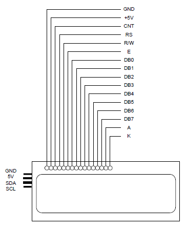
LCD1602のピン配置
LCD1602のピン配置は以下の様になっているらしい。上から順番に1~16。

各ピンの意味は以下の通り。
| GND | Ground |
| +5V | Vcc(電源) |
| CNT | L→H→LでDB0~DB7ピンと信号伝送 |
| RS | Register Select -> H: Data, L: Command |
| R/W | H: Read, L: Write |
| E | L→H→LでDB0~DB7ピンと信号伝送 |
| DB0~DB7 | 8ビットデータ |
| A | LEDのアノード |
| K | LEDのカソード |
表示領域~DDRAM
2行表示の場合のDDRAMアドレスの割り当ては以下の様になっている。

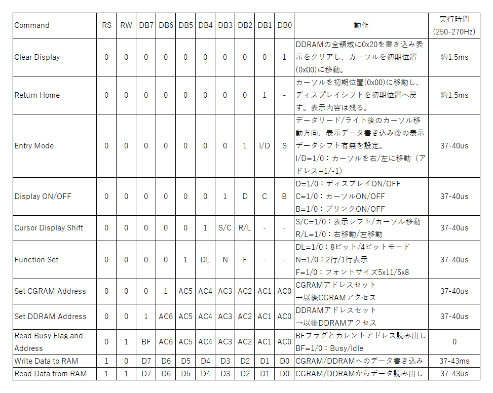
LCD1602のコマンド
LCD1602のコマンドは以下の通り。H→1、L→0で表している。
- RS=0のときはコマンド、RS=1のときはデータを表す
- R/W=1で読み出し、R/W=0で書き込みで、コマンドは常にR/W=0
- コマンドの場合は8ビットのDB7~0で最初に1が現れたビットによってコマンドが変わる
- 書き込み/読み出しは、EをL→H→Lと変化させて実行

8ビット/4ビットモードの設定
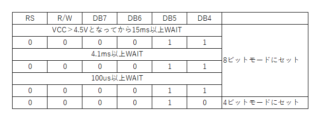
LCD1602起動時、確実に8ビット/4ビットモードをセットする手順は以下の通り。

起動直後の初期設定では、適切な待機時間を挟んで4ビットで0x3を3回書き込んだ後に0x2を書き込むことで4ビットモードに設定される。
I2CによるLCD1602の制御
接続
キットのLCD1602にはあらかじめI2C接続のためのボードが接続されていた。チップはHLF8574Tと書かれていたが、これは中国製らしくフィリップス製のPCF8574と同じ機能らしい。PCF8574はI2C I/Oエクスパンダ―というチップで、I2Cに準拠しSDAを介したシリアルの通信と、P0~P7の8ビットパラレルの通信を変換する。
PCF8574のP0~P7が8ビットのレジスターの各ビットに相当し、それらはLCD1602の各ピンと以下のように接続されている(他のピンは省略している)。
参考サイト:
| PCF8574 | LCD1602 | LCD1602の機能 |
| P7 | DB7 | 4ビットデータのbit3 |
| P6 | DB6 | 4ビットデータのbit2 |
| P5 | DB5 | 4ビットデータのbit1 |
| P4 | DB4 | 4ビットデータのbit0 |
| P3 | K | バックライトのカソード |
| P2 | E | L→H→LでDB0~DB7ピンと信号伝送 |
| P1 | R/W | H: Read, L: Write |
| P0 | RS | Register Select -> H: Data, L: Command |
DB0~DB3は接続されていないことから、このモジュールは常に4ビットモードで使用する必要がある。
P2に接続されたKピンはバックライトのカソードにあたり、トランジスターのC~Bを介してGNDに接続されている。
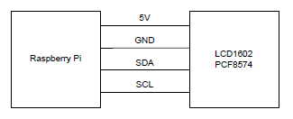
LCDとRaspiの接続
Rasberey PiのGPIO2と3(3番ピンと5番ピン)がSDAとSCLに対応しており、電源・GNDとともにこれらをLCDの端子(正確にはLCDに接続されたエキスパンダーの端子)に接続する。
SDAとSCLに対するプルアップ抵抗がないが、LCD/I2C内部でプルアップされているらしい。

初期手順
Raspberry Piの手順に従ってI2Cを有効化した後、デバイスアドレスを確認(I2Cを参照)。ここでは、LCD1602のデバイスアドレスは0x27。
|
1 2 3 4 5 6 7 8 9 10 |
$ i2cdetect -y 1 0 1 2 3 4 5 6 7 8 9 a b c d e f 00: -- -- -- -- -- -- -- -- -- -- -- -- -- 10: -- -- -- -- -- -- -- -- -- -- -- -- -- -- -- -- 20: -- -- -- -- -- -- -- 27 -- -- -- -- -- -- -- -- 30: -- -- -- -- -- -- -- -- -- -- -- -- -- -- -- -- 40: -- -- -- -- -- -- -- -- -- -- -- -- -- -- -- -- 50: -- -- -- -- -- -- -- -- -- -- -- -- -- -- -- -- 60: -- -- -- -- -- -- -- -- -- -- -- -- -- -- -- -- 70: -- -- -- -- -- -- -- -- |
コード
動作テスト
LCDモジュールを4ビットモードにセット後、画面をクリアしてカーソルをブリンクさせる。
|
1 2 3 4 5 6 7 8 9 10 11 12 13 14 15 16 17 18 19 20 21 22 23 24 25 26 27 28 29 30 31 32 33 34 35 36 37 38 39 40 41 42 43 44 45 46 47 48 49 50 51 52 53 54 55 |
import smbus2 as smbus import time # Set constants BUS = smbus.SMBus(1) LCD_ADDR = 0x27 TW = 0.001 # pulse with for enable # Write 4bits def write_4bits(bits): buf = bits << 4 # 0xC: BL=1, E=1, R/W=0, RS=0 BUS.write_byte(LCD_ADDR, buf | 0x0C) time.sleep(TW) # 0xFB: 1011 -> only E=0 BUS.write_byte(LCD_ADDR, buf & 0xFB) # Write one byte command by dividing higher and lower 4bits def write_command(command): # Write higher bits buf = command & 0xF0 | 0x0C BUS.write_byte(LCD_ADDR, buf) time.sleep(TW) BUS.write_byte(LCD_ADDR, buf & 0xFB) # Write lower bits buf = (command << 4) | 0x0C BUS.write_byte(LCD_ADDR, buf) time.sleep(TW) BUS.write_byte(LCD_ADDR, buf & 0xFB) # Set 8bit mode initially write_4bits(0x3) time.sleep(0.005) write_4bits(0x3) time.sleep(0.001) write_4bits(0x3) # Set 4bit mode write_4bits(0x2) # Commands # Function set: 001(DL)|NFxx # DL=0(4bit mode) # N=1(2 lines) # F=0(5x8 font) write_command(0x28) time.sleep(0.002) # Display ON/OFF: 0000|1DCB # D=1(display ON) # C=1(Cursor ON) # B=1(Blink ON) write_command(0x0F) time.sleep(0.002) # Clear Display: 0000|0001 write_command(0x01) time.sleep(0.002) |
冒頭で定数を定義している。TWはEを1にしてからLに戻すまでの待機時間で、データシートでは最小230nsという値もあったが、Pythonのtime.sleepの分解能もあり、1ms(以上)としている。
|
1 2 3 4 |
# Set constants BUS = smbus.SMBus(1) LCD_ADDR = 0x27 TW = 0.001 # pulse with for enable |
次に、4ビットのデータを書き込む関数を定義している。
- 引数のデータの下位4ビットを取り出し、4ビットシフトして上位4ビットへ
- 下位4ビットにコマンドセット
- バックライトON、転送Enable、Writeモード、コマンドレジスターに書き込み指示
- 書き込みウェイト
- EnableをLowにして書き込み
|
1 2 3 4 5 6 7 8 |
# Write 4bits def write_4bits(bits): buf = (bits & 0xF) << 4 # 0xC: BL=1, E=1, R/W=0, RS=0 BUS.write_byte(LCD_ADDR, buf | 0x0C) time.sleep(TW) # 0xFB: 1011 -> only E=0 BUS.write_byte(LCD_ADDR, buf & 0xFB) |
もう1つの関数は、1バイトのコマンドをLCDに書き込む。4ビットモードなので上位・下位の4ビットに分けて書き込んでいる。
コマンド送信の場合の手順は、上位4ビットの場合は0xF0でマスク、下位4ビットの場合は0xFでマスクして4ビット分シフトした後、以下の通り。
- 下位4ビットはコマンド書き込みイネーブルで、KE(RW)(RS)=0b1100=0xC
TWの間ウェイト- その後Eのみ0とするため0b11111011=0xFBでマスクして書き込み
|
1 2 3 4 5 6 7 8 9 10 11 12 |
# Write one byte command by dividing higher and lower 4bits def write_command(command): # Write higher bits buf = command & 0xF0 | 0x0C BUS.write_byte(LCD_ADDR, buf) time.sleep(TW) BUS.write_byte(LCD_ADDR, buf & 0xFB) # Write lower bits buf = ((command & 0xF) << 4) | 0x0C BUS.write_byte(LCD_ADDR, buf) time.sleep(TW) BUS.write_byte(LCD_ADDR, buf & 0xFB) |
実行部分の先頭で、8ビットモードを確定してから4ビットモードを設定。
いろいろなサンプルコードで0x33→0x32とバイト単位で書き込む例が多いが、4ビットごとの待機時間を意識するならこの方がデータシートの説明とも合っている。
|
1 2 3 4 5 6 7 8 |
# Set 8bit mode initially write_4bits(0x3) time.sleep(0.005) write_4bits(0x3) time.sleep(0.001) write_4bits(0x3) # Set 4bit mode write_4bits(0x2) |
最後にコマンド送信。
|
1 2 3 4 5 6 7 8 9 10 11 12 13 14 15 16 |
# Commands # Function set: 001(DL)|NFxx # DL=0(4bit mode) # N=1(2 lines) # F=0(5x8 font) write_command(0x28) time.sleep(0.002) # Display ON/OFF: 0000|1DCB # D=1(display ON) # C=1(Cursor ON) # B=1(Blink ON) write_command(0x0F) time.sleep(0.002) # Clear Display: 0000|0001 write_command(0x01) time.sleep(0.002) |
まず001で始まるFunction setで0b00101000=0x28とする。
- DL=0で4ビットモード
- N=1で2行表示
- F=0で5×8フォントを使用
次に00001で始まるDisplay ONで0b00001111=0x0Fとする。
- D=1でディスプレイ表示
- C=1でカーソル表示
- B=1でブリンクさせる
最後に0b00000001=0x01でディスプレイをクリア。
文字表示
先のコードに変更・追加を加えて、LCDに文字を表示してみる。
|
1 2 3 4 5 6 7 8 9 10 11 12 13 14 15 16 17 18 19 20 21 22 23 24 25 26 27 28 29 30 31 32 33 34 35 36 37 38 39 40 41 42 43 44 45 46 47 48 49 50 51 52 53 54 55 56 57 58 59 60 61 62 63 64 65 66 67 |
import smbus2 as smbus import time # Set constants BUS = smbus.SMBus(1) LCD_ADDR = 0x27 TW = 0.001 # pulse with for enable # Write 4bits def write_4bits(bits): buf = (bits & 0xF) << 4 # 0xC: BL=1, E=1, R/W=0, RS=0 BUS.write_byte(LCD_ADDR, buf | 0x0C) time.sleep(TW) # 0xFB: 1011 -> only E=0 BUS.write_byte(LCD_ADDR, buf & 0xFB) # Write one byte command by dividing higher and lower 4bits def write_byte(command, is_command): lower_bits = 0x0C if is_command else 0x0D # Write higher bits buf = command & 0xF0 | lower_bits BUS.write_byte(LCD_ADDR, buf) time.sleep(TW) BUS.write_byte(LCD_ADDR, buf & 0xFB) # Write lower bits buf = ((command & 0xF) << 4) | lower_bits BUS.write_byte(LCD_ADDR, buf) time.sleep(TW) BUS.write_byte(LCD_ADDR, buf & 0xFB) # Write a character to specified addres def write_char(char, addr=None): # Set address if specified if addr: write_byte(0x80 | (addr & 0xFF), is_command=True) # Write character to current addres write_byte(char, is_command=False) # Set 8bit mode initially write_4bits(0x3) time.sleep(0.005) write_4bits(0x3) time.sleep(0.001) write_4bits(0x3) # Set 4bit mode write_4bits(0x2) # Commands # Function set: 001(DL)|NFxx # DL=0(4bit mode), N=1(2 lines), F=0(5x8 font) write_byte(0x28, is_command=True) # Display ON/OFF: 0000|1DCB # D=1(display ON), C=0(Cursor OFF), B=0(Blink OFF) write_byte(0x0C, is_command=True) # Clear Display: 0000|0001 write_byte(0x01, is_command=True) # Write characters # First line - alphabet write_char(0x41, 0x00) write_char(0x42) write_char(0x43) # Second line - kana write_char(0xB1, 0x40) write_char(0xB2) write_char(0xB3) |
まず、write_command関数をwrite_byte関数に変更し、引数is_commandのTrue/Falseに応じてRSの0/1を切替え、コマンド・データの両方を取り扱えるようにした。
データ送信の場合イネーブル時にRS=0となるため、下位4ビットはKE(RW)(RS)=0b1101=0xDとなる
|
1 2 3 4 5 6 7 8 9 10 11 12 13 |
# Write one byte command by dividing higher and lower 4bits def write_byte(command, is_command): lower_bits = 0x0C if is_command else 0x0D # Write higher bits buf = command & 0xF0 | lower_bits BUS.write_byte(LCD_ADDR, buf) time.sleep(TW) BUS.write_byte(LCD_ADDR, buf & 0xFB) # Write lower bits buf = ((command & 0xF) << 4) | lower_bits BUS.write_byte(LCD_ADDR, buf) time.sleep(TW) BUS.write_byte(LCD_ADDR, buf & 0xFB) |
また、新たに文字を表示する関数write_charを定義した。アドレスが与えられた場合はDDRAMのそのアドレスに、アドレスを指定しない場合は現在のアドレスに文字を書き込む。1文字書き込むとアドレスはインクリメントされるため、続けて文字を書き込む場合にはアドレス指定はしなくてよい。
|
1 2 3 4 5 6 7 |
# Write a character to specified addres def write_char(char, addr=None): # Set address if specified if addr: write_byte(0x80 | (addr & 0xFF), is_command=True) # Write character to current addres write_byte(char, is_command=False) |
実行の前半では、カーソルOFF、ブリンクOFFとしている。
|
1 2 3 |
# Display ON/OFF: 0000|1DCB # D=1(display ON), C=0(Cursor OFF), B=0(Blink OFF) write_byte(0x0C, is_command=True) |
文字表示の部分は以下の通りで、1行目に”ABC”、2行目に半角カナで”アイウ”と表示している。
|
1 2 3 4 5 6 7 8 9 |
# Write characters # First line - alphabet write_char(0x41, 0x00) write_char(0x42) write_char(0x43) # Second line - kana write_char(0xB1, 0x40) write_char(0xB2) write_char(0xB3) |
LCD1602クラス
LCD1602を扱うクラスを作成。これまで作った関数をクラスのメソッドにしただけ。インスタンス生成時にLCDのアドレスを与える。
|
1 2 3 4 5 6 7 8 9 10 11 12 13 14 15 16 17 18 19 20 21 22 23 24 25 26 27 28 29 30 31 32 33 34 35 36 37 38 39 40 41 42 43 44 45 46 47 48 49 50 51 52 53 54 55 56 57 58 59 60 61 62 63 64 65 66 67 68 69 70 71 72 73 74 75 76 77 78 79 80 |
import smbus2 as smbus import time # Class to manipuoate LCD1602 class LCD1602: # Set constants BUS = smbus.SMBus(1) TW = 0.001 # pulse with for enable # Create an instance by specifying LCD Address def __init__(self, lcd_addr): self.lcd_addr = lcd_addr # Set 8bit mode initially self._write_4bits(0x3) time.sleep(0.005) self._write_4bits(0x3) time.sleep(0.001) self._write_4bits(0x3) # Set 4bit mode self._write_4bits(0x2) # Commands # Function set: 001(DL)|NFxx # DL=0(4bit mode), N=1(2 lines), F=0(5x8 font) self._write_byte(0x28, is_command=True) # Display ON/OFF: 0000|1DCB # D=1(display ON), C=0(Cursor OFF), B=0(Blink OFF) self._write_byte(0x0C, is_command=True) # Clear Display: 0000|0001 self._write_byte(0x01, is_command=True) # Write 4bits def _write_4bits(self, bits): buf = (bits & 0xF) << 4 # 0xC: BL=1, E=1, R/W=0, RS=0 self.BUS.write_byte(self.lcd_addr, buf | 0x0C) time.sleep(self.TW) # 0xFB: 1011 -> only E=0 self.BUS.write_byte(self.lcd_addr, buf & 0xFB) # Write one byte command by dividing higher and lower 4bits def _write_byte(self, command, is_command): lower_bits = 0x0C if is_command else 0x0D # Write higher bits buf = command & 0xF0 | lower_bits self.BUS.write_byte(self.lcd_addr, buf) time.sleep(self.TW) self.BUS.write_byte(self.lcd_addr, buf & 0xFB) # Write lower bits buf = ((command & 0xF) << 4) | lower_bits self.BUS.write_byte(self.lcd_addr, buf) time.sleep(self.TW) self.BUS.write_byte(self.lcd_addr, buf & 0xFB) # Write a character to specified addres def write_char(self, char_cord, addr=None): # Set address if specified if addr: self._write_byte(0x80 | (addr & 0xFF), is_command=True) # Write character to current addres self._write_byte(char_cord, is_command=False) # Write string specifying line and start position def write_string(self, str, line=1, start_pos=1): addr = 0x00 if line==1 else 0x40 addr += start_pos for char in str: self.write_char(ord(char), addr) addr += 1 # Create instance of LCD lcd = LCD1602(0x27) # Write string to the first line lcd.write_string('Welcome', line=1, start_pos=4) # Write characters to the second line ('Youkoso' in Kana) lcd.write_char(0xD6, 0x45) lcd.write_char(0xB3) lcd.write_char(0xBA) lcd.write_char(0xBF) |